|
 |
This install takes 10 - 20 minutes. This is a very easy install that requires no special tools or any real skills.
Click on the images for larger views. |
Step 1: Getting the required items together
This install requires:
- Valentine V1 Detector
- Following Items Included w/Detector
- Direct-wire power adapter
- Windshield mount
- Power cord
- Interlocking fastener
- Philips Screwdriver.
- Flat Screwdriver (or something else to pry with)
- Electrical Tape or Zip Tie
- A BMW M3 (E46).
- 10 to 20 minutes of free time.
- OPTIONAL (but recommended): You may want to purchase a 12" or so jumper phone cord (2 line) to use rather than the included power cord as this will require less bundling of wires under the universal transmitter panel. Radio Shack typically has these for around $3.
|
 |
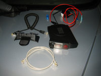
Valentine V1 and Items for Install |
Step 2: Removing the Center Light Fixture
- Get in the driver's side of the car.
- Using your flat screwdriver (I used a bicycle tire lever to avoid scratching things), carefully pry open the driver's rear corner of the light fixture (see image).
- Once you can get your fingers under the edge of the fixture carefully rotate it down and forward (toward the windshield) to release (see image).
- Once the rear of the fixture is free, pull the light fixture down. You can either leave it hanging by its electrical connection or unplug it and set it aside (recommended - simply press the side tabs on the connector and pull it back - see image).
|
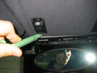
Prying Open Light

Removing Light
Disconnecting Electrical Connector |
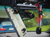
Step 3: Removing the Sunroof Switch / Univ. Transmitter Panel
- There is a little bit of a trick to this - right behind the front edge of the panel there is a metal bar.
- The trick is to get your finger right behind the bar and gently push the front of the panel down (see first image).
- Once the front is released pull the rest of the panel down - let it hang down by the sunroof power connector.
|
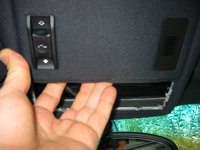
Removing Panel
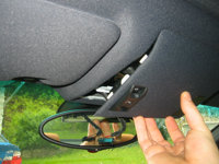
Removing Panel |
Step 4: Connecting the Ground
- Locate the silver screw in the opening for the light fixture (see image).
- Loosen this screw a few turns, but do not remove it completely.
- Thread the ground wire (black wire with spade lug connector from the direct-wire adapter) through the opening for the univ. transmitter panel and over the metal brace into the opening for the light fixture.
- Slide the spade lug under the screw (it make take a little push to get it on to the screw) and tighten the screw down (see image).
|
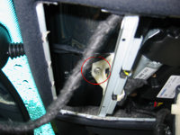
Locating a Good Ground
Attaching the Ground Wire |
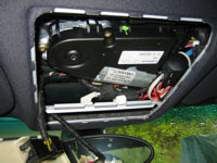
Step 5: Fishing Out the Power Lead
- The power source for the universal transmitter is neatly tucked in along the right edge of the panel opening (see image).
- The connector is bundled up in a fabric like insulating material.
- Unwrap only enough insulation to access the connector plug and about the first 2" of wire behind it (see image).
|
Location of Power Harness
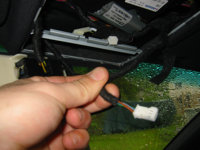
Exposed Connector |
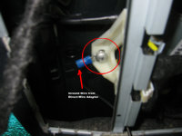
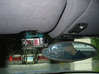
Step 6: Getting Some Voltage
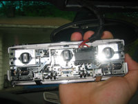
- There are 3 wires to the universal transmitter connector - We need the green one (has a stripe, I believe blue on it as well). Do not disconnect the wire from the connector!
- Take the Interlocking Fastener and place the green wire from the connector in the slit in the metal section of the fastener (see image). Don't worry about forcing it down in the metal clip.
- Close the faster until it snaps together and then gently squeeze it together with a set of pliers in order to force the wire down into the metal section of the fastener.
- The Red Wire on the direct-wire adapter has a connector at the end - slide this connector into the end of the now closed interlocking fastener (see image).
|
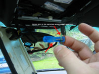
Fastener on Power Wire
Power Lead Connected |
Step 7: A Quick Test
- Plug the power cord into the now wired up direct wire connector ("main unit" socket) and into the detector itself.
- Turn your ignition to the second click (the position it would be in if the car was running) and see if your detector powers up.
- If the detector does not power up, make sure its on (dah), make sure the power cord is in the correct socket in the direct wire adapter, make sure the ignition is in the correct position.
- If the above does not work, check the fuse (unscrew the little black round case along the red power wire from the direct wire adapter to access fuse).
- If all of the above checks out and you still have no power, check your ground and power connections (steps 4 & 6).
- If everything is kosher, go to the next step.
|
Plugging In |
Step 8: Running the Power Cord Out
- Now that you know everything works, unplug the power cord from the detector.
- Run the end of the power cord over the metal brace between the light and univ. transmitter panels.
- Look through the light fixture opening toward the windshield and you will see a small gap between the glass and the headliner.
- Carefully work the end of the power cord through the gap to which ever side you will want to mount the detector.
- Pull about 6" of the cord out through the edge of the headliner in all.
|
|
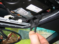
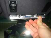
Step 9: Tiding Up
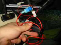
- Carefully and cleanly bundle up the extra wires and wrap them with electrical tape or a zip tie to keep them together (see image).
- Make sure you do not pull the power cord back through the headliner when bundling the wires up.
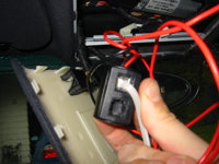
- There is enough room to stuff the wiring and direct wire connector up in the right side of the panel - do so gently and carefully (see image).
- If you used the stock power cord you may want to not bundle that with the direct wire adapter and bundle it in the front opening over the light fixture.
|
Bundling Up
Stowing Away |
Step 9: Closing the Univ. Transmitter Panel
- Line up the rear edge of the univ. transmitter panel with the back endge of the opening (see image).
- Push the panel up into place - it will snap in when properly seated - DO NOT FORCE IT!
|
Installing the Panel |
Step 10: Reinstalling the Light Fixture
- If you disconnected the light fixture, plug it back in at this time.
- Line up the front edge of the light fixture with the front edge of the opening and rotate it up and into place (see image).
- Panel will snap in when properly seated - do not force it.
|
Installing the Light |
Step 11: Mount the Detector
- Mount the detector in the windshield mount so that the detector itself is just below the tinted line on the windshield.
- Make sure the detector is level.
- Make sure the detector is in parallel with the centerline of the car and that the rear antenna is not obstructed by anything in the vehicle.
- Drive safely!
|
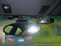
Detector to the Right
Detector to the Left |

|